
Well Testing & Commissioning
Surface Test Tree
The Surface Test Tree (STT), also known as the Flowhead, is located directly on top of the well and serves as the first piece of equipment that well fluid passes through. Its primary function is to control the flow of fluid into and out of the well.
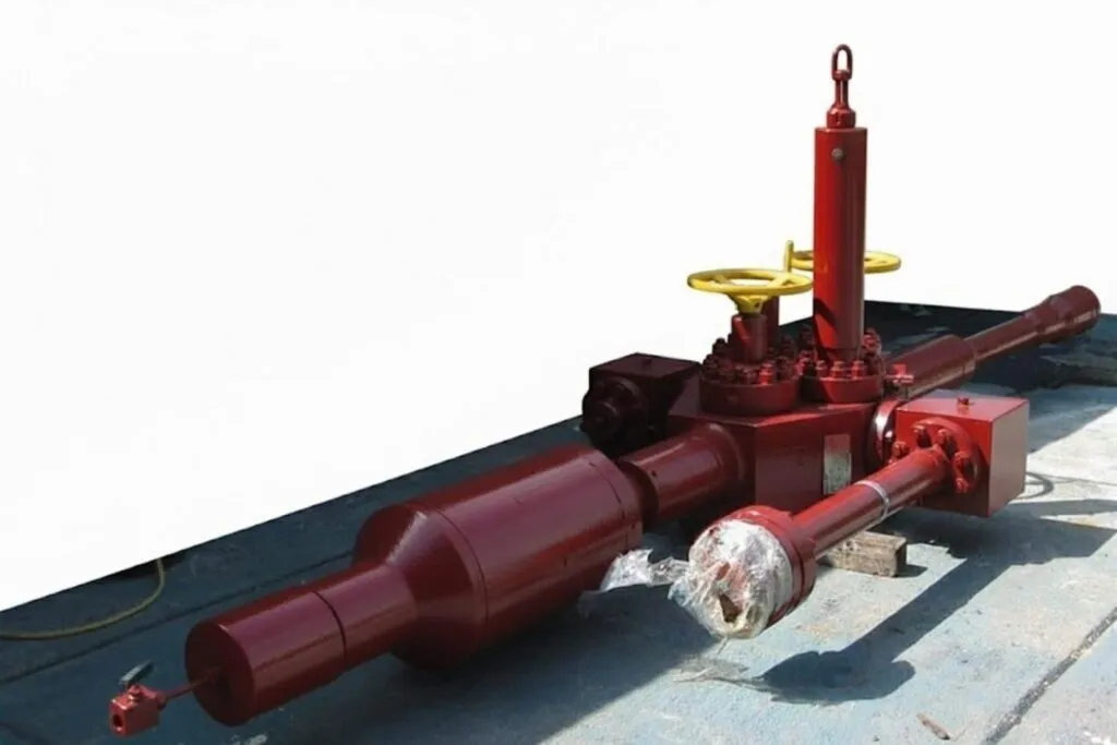
The Surface Test Tree (STT), also known as the Flowhead, is located directly on top of the well and serves as the first piece of equipment that well fluid passes through. Its primary function is to control the flow of fluid into and out of the well.
The size and number of components in the Surface Test Tree depend on the type of test being performed and the rig used. The minimum required equipment includes:
The STT incorporates a central body that contains the following components:
Additionally, each tree is supplied with wing blocks that are attached to enable flexible flow lines to be connected to the surface tree.
The Surface Test Tree can be adapted to various sizes of tubing or drill pipe through the use of a crossover sub.
The test trees are available in models with 10,000 psi and 15,000 psi working pressure. The configuration has a variable tensile rating, dependent on connection type, size, pressure, and temperature.
To complement the standard configuration, several additional components are available to enhance flexibility:
The flow wing valve is controlled by a hydraulic actuator, which can be integrated with an Emergency Shutdown System (ESD). A manual wing valve is typically used for kill line connection, circulating procedures, or stimulation.
Slickline, coiled tubing, or electric line operations can be performed through the STT swab valve by connecting BOP’s and a lubricator to the top connection of the STT.
The swivel, an integral part of the STT assembly, is installed between the STT block and the work string or tubing. Its primary function is to allow the rotation of the work string or tubing for manipulation of downhole equipment without turning the STT and the flexible flowlines attached to it.
A check valve can be installed on the kill side of the STT, preventing well effluent from flowing back through the kill line into the kill pumps, which allows the kill valve to remain open for emergency purposes during testing operations.
The lower master valve adds an additional layer of safety. In the event of a leak occurring above the valve, it can be closed to allow for repairs. It also helps pressure test the installation above the rotary table and prevents test fluid and pressure from entering the test string.
The lower master valve can be used when multiple valve isolation of the work string or tubing is needed.
Meets requirements of NACE MR0175. Transportation skid included.
Other sizes, configurations, and pressure ratings are available to meet most applications. For more information, please contact your local Apex Petroleum Services representative.
Sales of Apex Petroleum products and services will be in accordance solely with the terms and conditions contained in the contract between Apex Petroleum and the customer that is applicable to the sale.
Key features
- Meets applicable industry standards for added safety.
- Additional components can be added for flexibility.
- Can be third-party certified according to required standards.
- A flapper or check valve is set at the inlet of the killing line.
- The swivel enables rotation of the test string for packer setting and disconnect operations.
Specifications
Scroll horizontally to view the complete table
| Surface Test Tree Specifications | ||||||||
|---|---|---|---|---|---|---|---|---|
| Size and Description | Working Pressure (Psi) | Working Temp.F | End Connections | Flanges | Crossovers | Design Code | Handling Sub | Tensile Rating (lb) |
| 3 -1/16″ | 10,000 | -50 to 250 | 5 3/4″ – 4Stub Acme Box | 3 1/16″ API 6A, Bx 15410,000 psi | 3 1/16″ API6A, Bx 154x Fig 1502 hammer union | API 6A, ANSI B31.3, NACEMR-01-75, PSL 3 | 5 3/4″ – 4Stub Acme Box x Pin | 660,000 @ MAWP@ 250° F570,000 @ MAWP@ 350° F |
| 3 -1/16″ | 10,000 | -50 to 350 | 5 3/4″ – 4Stub Acme Box | 3 1/16″ API 6A, Bx 15410,000 psi | 3 1/16″ API6A, Bx 154x Fig 1502 hammer union | API 6A, ANSI B31.3, NACEMR-01-75, | 5 3/4″ – 4Stub Acme Box x Pin | 660,000 @ MAWP@ 250° F570,000 @ MAWP@ 350° F |
| PSL 3 | ||||||||
| 3- 1/16″ | 15,000 | -50 to 350 | 5 3/4″ – 4Stub Acme Box | 3 1/16″ API 6A, Bx 15415,000 psi | 3 1/16″ API6A, Bx 154x Fig 2202 hammer union | API 6A, ANSI B31.3, NACEMR-01-75, PSL 3 | 5 3/4″ – 4Stub Acme Box x Pin | 450,000 @ MAWP@ 250° F480,000 @ 12,500 psi@ 350° F |
| 5 -1/8″ | 10,000 | -50 to 250 | Top: 8¼” – 4SA (F)Bottom: 8¼” 4SA (F) | 3 1/16″ API 6A,- Bx 15410,000 psi | 5-1/8″ API6A, flange x/overx Fig 1502 hammer union | API 6A, ANSI B31.3, NACEMR-01-75, PSL 3 | 8 -1/4″ – 4Stub Acme Box x Pin | 580,000 @ MAWP@ 250° F460,000 @ 9,700 psi@ 350° F |
Scroll horizontally to view the complete table
| Surface Test Tree | |
|---|---|
| Type | Description |
| Check Valve | Check Valve – 3 1/16″ 10K, API 6A, Bx 154 Flange, w/Lockout Pin, NACE Service |
| Check Valve | Check Valve – 3 1/16″ 15K, API 6A, Bx 154 Flange, w/Lockout Pin, NACE Service |
| Swivel | 3 1/16″ ID 10K Swivel Assembly, 5 3/4″ – 4 Stub Acme Pin x Pin, NACE Service |
| Swivel | 3 1/16″ ID 15K Swivel Assembly, 5 3/4″ – 4 Stub Acme Pin x Pin, NACE Service |
| Swivel | 5 1/8″ ID 10K Swivel Assembly, 7 1/2″ – 4 Stub Acme Box x Pin, NACE Service |
| Lower Master Valve | 3 1/16″ 10K Lower Master Valve w/Actuator, 5 3/4″ – 4 Stub Acme Box x Pin, NACE Service |
| Lower Master Valve | 3 1/16″ 15K Lower Master Valve w/Actuator, 5 3/4″ – 4 Stub Acme Box x Pin, NACE Service |
| Stiff Joint | Stiff Joint – 3″ ID 10K, 5 3/4″ – 4 Stub Acme Box x Pin, NACE Service, Various Lengths |
| Stiff Joint | Stiff Joint – 3″ ID 15K, 5 3/4″ – 4 Stub Acme Box x Pin, NACE Service, Various Lengths |
Related products
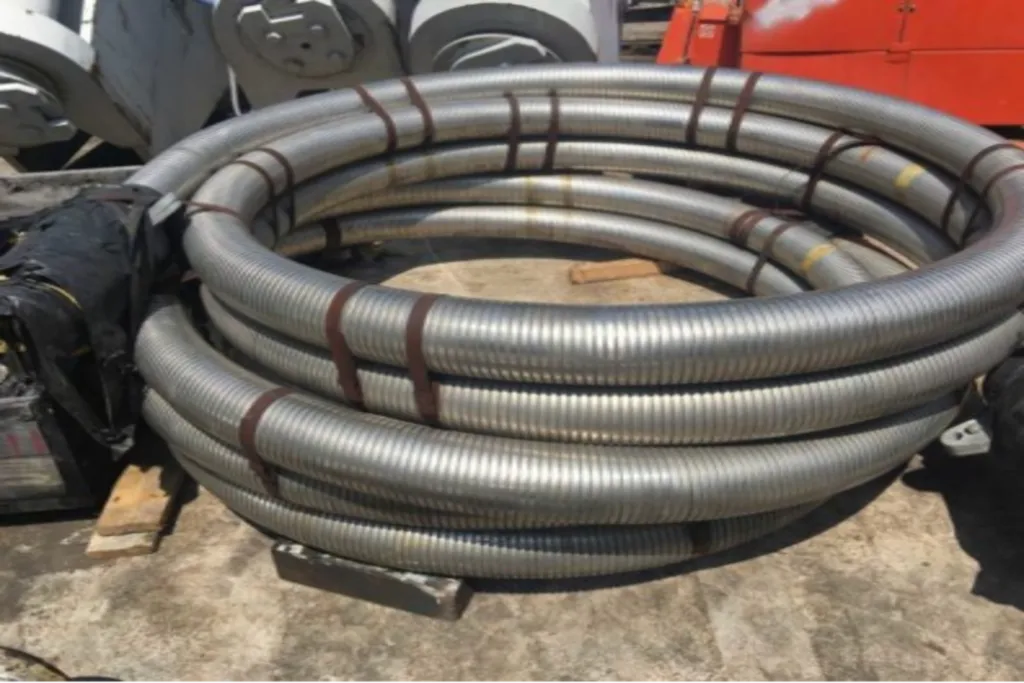
Coflexip Hose (Flexible Armored)
The Apex Petroleum Services Flexible Armored Hose is generally used for 5000, 10,000 psi, and 15,000 psi applications to replace hard piping where any expansion in the work string and movement may occur.
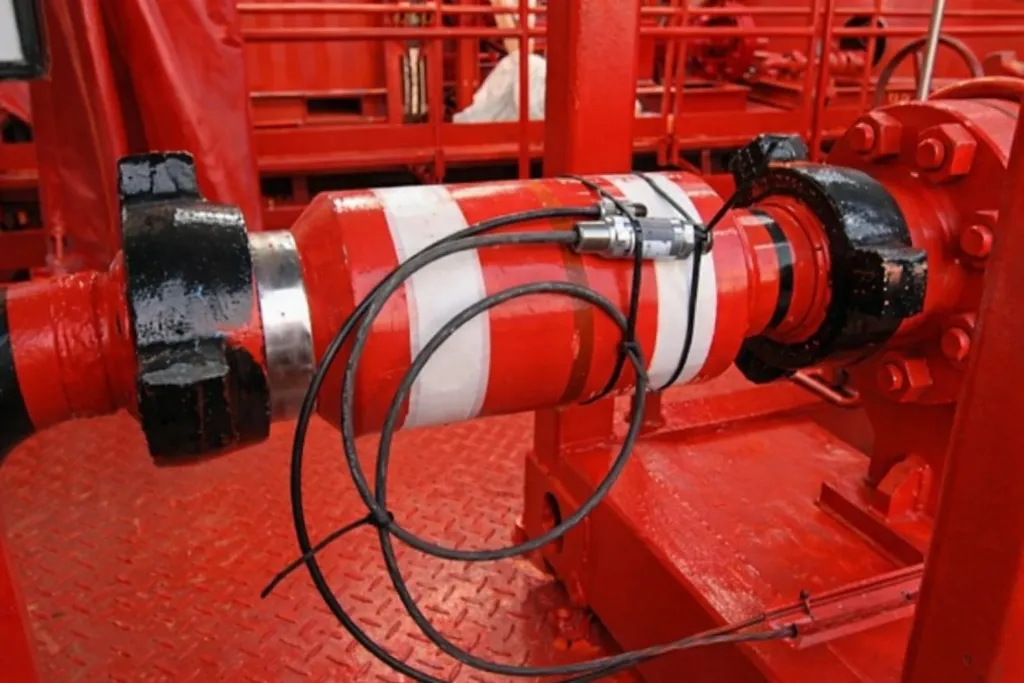
Data Header
The Data Header is a piping component with several ports along or around its length that provide access to the flow stream for sampling, monitoring of pressure and temperature, sand/silt monitoring, and chemical injection.
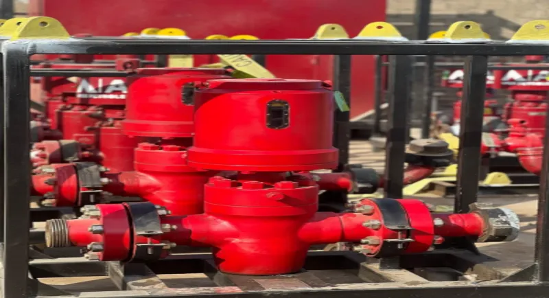
Surface Safety Valve
Inline Surface Safety Valves are installed upstream of the choke manifold to provide quick response valve closure, isolating the system in case of line or vessel rupture.
Need this equipment on site?
Talk to our engineering team about specifications, availability, and deployment.