
Well Testing & Commissioning
Debris Catcher
APEX’s debris catcher manifold is engineered to effectively remove drilling solids, formation particles, and proppant-based debris from wellbore fluids during well testing operations. Designed with operational efficiency and equipment protection in mind, the system safeguards downstream pressure control and measurement equipment from potential damage caused by debris-laden flow.
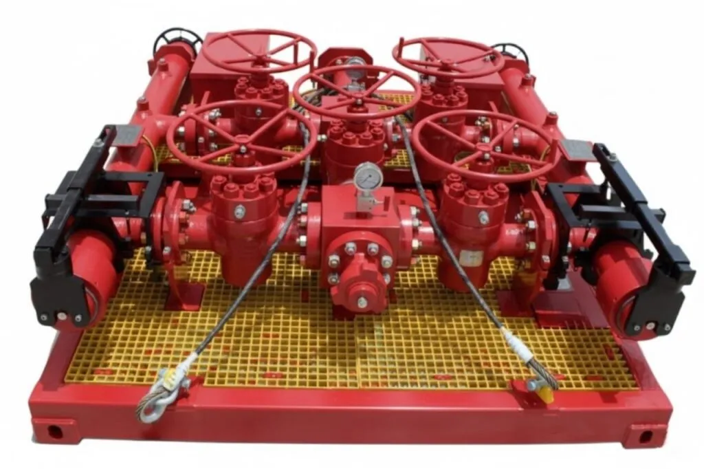
APEX’s debris catcher manifold is engineered to effectively remove drilling solids, formation particles, and proppant-based debris from wellbore fluids during well testing operations. Designed with operational efficiency and equipment protection in mind, the system safeguards downstream pressure control and measurement equipment from potential damage caused by debris-laden flow.
The manifold features two horizontal filter vessels—one on each side—equipped with independent upstream and downstream manual gate valves. This dual-path configuration allows for uninterrupted well testing flow while enabling the removal, cleaning, or replacement of filter screens without shutting down the operation.
Filter screens are available in a wide range of configurations, from junk-catcher types with customized slot or hole sizes to fine wire-wrapped sand filters with micron ratings of 200, 400, 800, and 1,200. Each screen includes a removable NPT plug at the closed end to support mechanical cleaning or flushing of stubborn debris.
APEX’s debris catcher manifold delivers a robust, flexible, and reliable solution for maintaining the integrity of well testing equipment and optimizing flow assurance.
Other sizes and configurations are available to meet most applications. For more information, contact your local Apex Petroleum Services representative.
Specifications
Scroll horizontally to view the complete table
| Specification | Model 1 | Model 2 |
|---|---|---|
| Maximum Working Pressure | 10,000 psi (690 bar) | 15,000 psi (1,034 bar) |
| Working Temperature | -20 to 250 °F (-29 to 121 °C) | -20 to 350 °F (-29 to 177 °C) |
| Nominal ID | 3 inches (76.2 mm) | 3 inches (76.2 mm) |
| Maximum Gas Rate | 35 MMscfd (991,090 m³/day) | 50 MMscfd (1,415,842 m³/day) |
| Maximum Liquid Rate | 5,000 bpd (795 m³/day) | 5,000 bpd (795 m³/day) |
| Weight (Dry) | 12,125 lbs (5,500 kg) | 16,535 lbs (7,500 kg) |
| External Dimensions (L x W x H) | 9.81 x 8 x 3.25 ft (2.99 x 2.44 x 0.99 m) | 9.81 x 8.69 x 3.61 ft (2.99 x 2.65 x 1.10 m) |
| Inlet/Outlet Connections | 3” 1502 female/male | 3 1/16” 15K flange or D27 hub |
| Drain/Flush Connections | 1-13/16” API flange / 1” AEMP female with pressure test blinds | 1-13/16” API flange / 1” AEMP female with pressure test blinds |
Related products
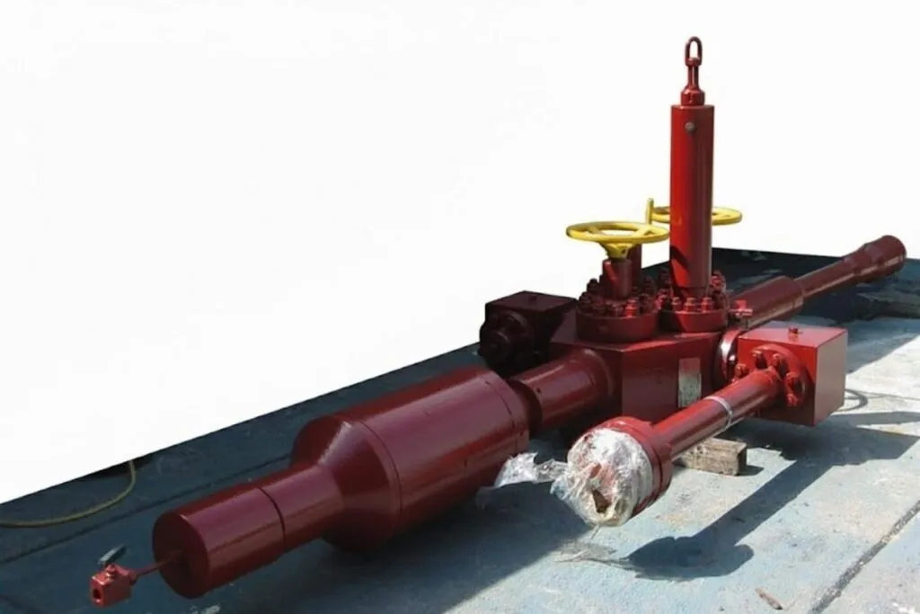
Surface Test Tree
The Surface Test Tree (STT), also known as the Flowhead, is located directly on top of the well and serves as the first piece of equipment that well fluid passes through. Its primary function is to control the flow of fluid into and out of the well.
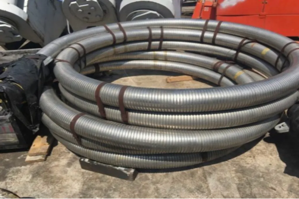
Coflexip Hose (Flexible Armored)
The Apex Petroleum Services Flexible Armored Hose is generally used for 5000, 10,000 psi, and 15,000 psi applications to replace hard piping where any expansion in the work string and movement may occur.
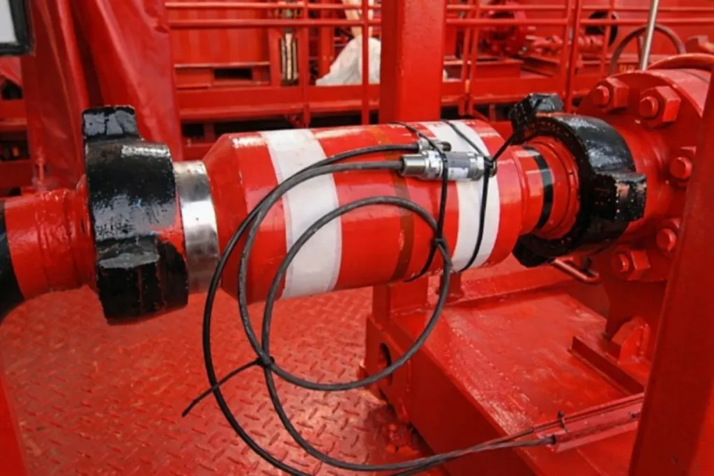
Data Header
The Data Header is a piping component with several ports along or around its length that provide access to the flow stream for sampling, monitoring of pressure and temperature, sand/silt monitoring, and chemical injection.
Need this equipment on site?
Talk to our engineering team about specifications, availability, and deployment.